- 您现在的位置:买卖IC网 > Sheet目录1168 > 71M6533-DB (Maxim Integrated Products)BOARD DEMO 71M6533
�� �
�
�71M6533-� DB� Demo� Board� User’s� Manual�
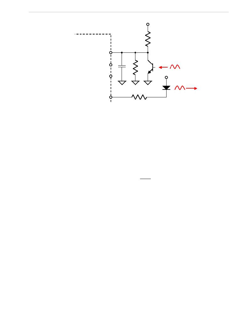
�V3P3SYS�
�71M6533�
�R� 1�
�OPT_RX�
�100pF�
�10k� Ω�
�R� 2�
�Phototransistor�
�V3P3SYS�
�LED�
�OPT_TX�
�Figure� 2-12:� Optical� Interface� Block� Diagram�
�The� IR� diode� should� be� connected� between� terminal� 2� of� header� J12� on� the� Demo� Board� (cathode)� and� the�
�V3P3� voltage� (anode),� which� is� accessible� at� terminal� 1� of� header� J12� (see� Figure� 3).�
�J12� on� the� 71M6533-DB� Demo� Boards� has� all� the� provisions� for� connecting� the� IR� LED� and� photo-transistor.�
�2.4.7� FERRITES�
�Ferrite� beads� on� the� PCB� are� useful� for� the� rejection� of� noise� and� general� EMI� events� such� as� ESD� and� EFT.�
�Some� precautions� apply:�
�1)�
�2)�
�Ferrites� should� not� be� placed� upstream� from� MOVs,� TVS,� and� other� clamping� devices,� since� large� currents�
�will� flow� through� the� ferrites� in� the� event� of� a� surge.� If� the� ferrite� is� not� designed� for� large� surge� currents,� it�
�will� burn� up.�
�Placing� ferrite� beads� directly� in� series� with� the� ADC� inputs� of� the� 71M6533� can� cause� inaccuracies� in� Wh�
�readings� over� temperature.� Ferrites� should� be� placed� before� the� balance� resistor� and� reservoir� capacitor.�
�For� details,� see� Maxim� Application� Note� AN-5292.�
�2.5�
�TESTING� THE� DEMO� BOARD�
�This� section� will� explain� how� the� 71M6533� IC� and� the� peripherals� can� be� tested.� Hints� given� in� this� section� will�
�help� evaluating� the� features� of� the� Demo� Board� and� understanding� the� IC� and� its� peripherals.�
�2.5.1� FUNCTIONAL� METER� TEST�
�This� is� the� test� that� every� Demo� Board� has� to� pass� before� being� integrated� into� a� Demo� Kit.� Before� going� into�
�the� functional� meter� test,� the� Demo� Board� has� already� passed� a� series� of� bench-top� tests,� but� the� functional�
�meter� test� is� the� first� test� that� applies� realistic� high� voltages� (and� current� signals� from� current� transformers)� to�
�the� Demo� Board.�
�Figure� 2-13� shows� a� meter� connected� to� a� typical� calibration� system.� The� calibrator� supplies� calibrated� voltage�
�and� current� signals� to� the� meter.� It� should� be� noted� that� the� current� flows� through� the� CT� or� CTs� that� are� not�
�part� of� the� Demo� Board.� The� Demo� Board� rather� receives� the� voltage� output� signals� from� the� CT.� An� optical�
�pickup� senses� the� pulses� emitted� by� the� meter� and� reports� them� to� the� calibrator.� Some� calibration� systems�
�have� electrical� pickups.� The� calibrator� measures� the� time� between� the� pulses� and� compares� it� to� the� expected�
�time,� based� on� the� meter� Kh� and� the� applied� power.�
�Page:� 49� of� 75�
�`�
�REV� 3�
�发布紧急采购,3分钟左右您将得到回复。
相关PDF资料
71M6534H-DB
BOARD DEMO 71M6534H
71M6541F-DB
DEMO BOARD 71M6541F
71M6543F-DB-CT
DEMO BOARD 71M6543F-DB-CT
72-CNV-5
CONVERTER RS-232 TO RS-422 5V
72346-001
72346-1-SCA-II REC
72347-001LF
CONN RECEPT SCA2 20POS VERT PCB
72436-001LF
80POS EXT HT. REC SCA-2
72442-201LF
CONN RECEPT SCA2 80POS VERT PCB
相关代理商/技术参数
71M6533G
制造商:MAXIM 制造商全称:Maxim Integrated Products 功能描述:Exceeds IEC 62053/ANSI C12.20 Standards
71M6533G-IGTR/F
功能描述:计量片上系统 - SoC AC Power Monitoring SoC-Programd RoHS:否 制造商:Maxim Integrated 核心:80515 MPU 处理器系列:71M6511 类型:Metering SoC 最大时钟频率:70 Hz 程序存储器大小:64 KB 数据 RAM 大小:7 KB 接口类型:UART 可编程输入/输出端数量:12 片上 ADC: 安装风格:SMD/SMT 封装 / 箱体:LQFP-64 封装:Reel
71M6533H
制造商:TERIDIAN 制造商全称:TERIDIAN 功能描述:Energy Meter IC
71M6533H-IEL
制造商:Maxim Integrated Products 功能描述:Metering Systems on a Chip - SoC Precision Energy Meter IC
71M6533H-IEL/F
制造商:Maxim Integrated Products 功能描述:Metering Systems on a Chip - SoC Precision Energy Meter IC
71M6533H-IELR
制造商:Maxim Integrated Products 功能描述:Metering Systems on a Chip - SoC Precision Energy Meter IC
71M6533H-IELR/F
制造商:Maxim Integrated Products 功能描述:Metering Systems on a Chip - SoC Precision Energy Meter IC
71M6533H-IGT/F
功能描述:计量片上系统 - SoC Precision Energy Meter IC RoHS:否 制造商:Maxim Integrated 核心:80515 MPU 处理器系列:71M6511 类型:Metering SoC 最大时钟频率:70 Hz 程序存储器大小:64 KB 数据 RAM 大小:7 KB 接口类型:UART 可编程输入/输出端数量:12 片上 ADC: 安装风格:SMD/SMT 封装 / 箱体:LQFP-64 封装:Reel